Fuses
Locate fuse and relay. Fuse box diagram. Identifying and legend fuse box from a Volkswagen Polo 6R (PQ25).
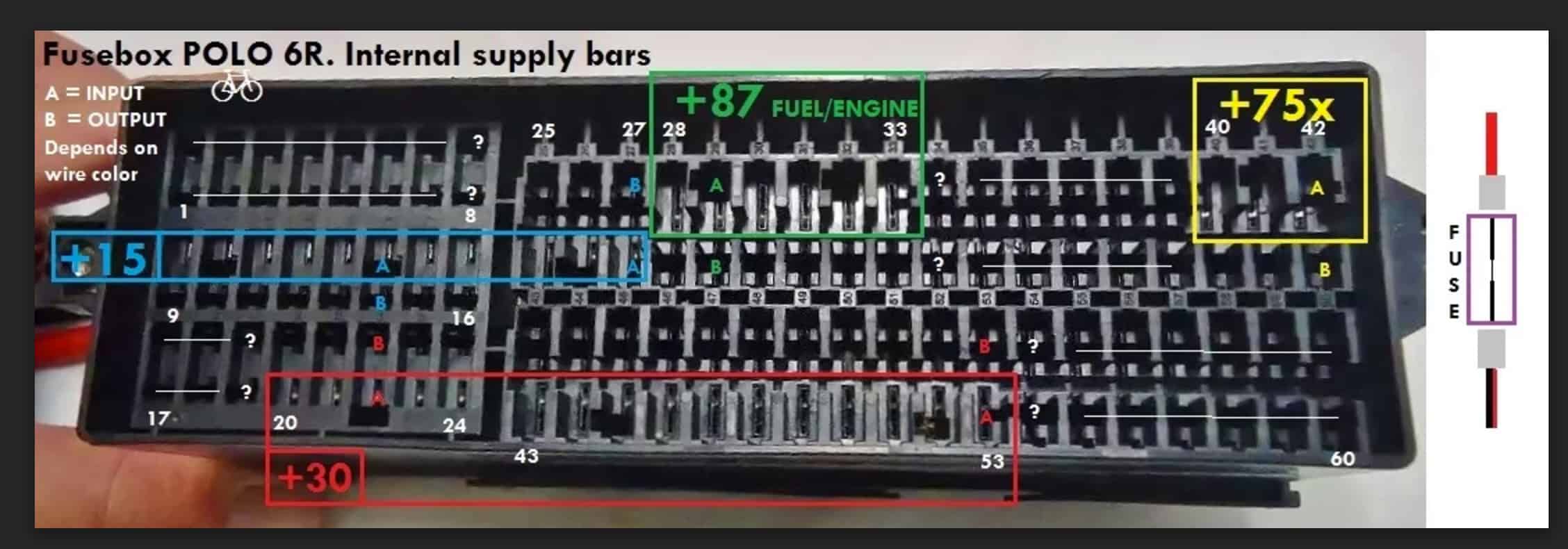
The reason the car does not come with a fuse card is that there are a huge number of fusing variations on the Polo 6R as you can see below.

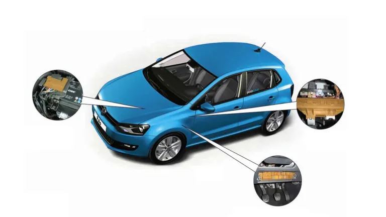
Overview of fuse and relay holders
- – Fuse holder A −SA−
Fuse holder C −SC− - – Fuse holder B −SB−
- Fitting location: under the steering wheel
- – Fuse holder F −SF−
- – Relay and fuse carrier 1 −SR1−

Fuse holder on the battery
- – Fuse holder A −SA−
- – Fuse holder C −SC−
- – Automatic glow period control unit −J179−
- Only models with diesel engine
Fuse holder A −SA− and fuse holder C −SC−
- – Fuse holder C −SC−
- – Fuse holder A −SA−
- – Additional coolant pump relay −J496−
- According to equipment

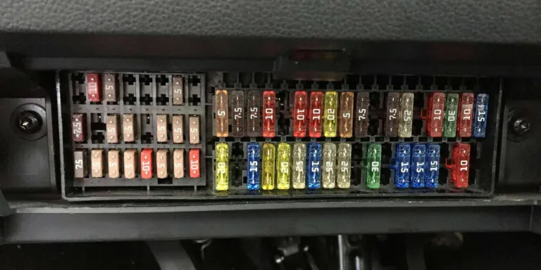
Fuse assignment on fuse holder A −SA−, fuse holder C −SC−
Fuse colours:
- 30 A – green
- 25 A – white
- 20 A – yellow
- 15 A – blue
- 10 A – red
- 7,5 A – brown
- 5 A – beige
- 3 A – purple

| No. | Current Flow Diagram designation | Nominal value | Function/component | Terminal |
|---|---|---|---|---|
| −SA1− | Fuse 1 on fuse holder A | 150A 175A | Alternator −C− | 30 |
| −SA2− | Fuse 2 on fuse holder A | Not assigned | ||
| −SA3− | Fuse 3 on fuse holder A | 110A |
| 30 |
| −SA4− | Fuse 4 on fuse holder A | 50A | Power steering control unit −J500− | 30 |
| −SA5− | Fuse 5 on fuse holder A | 40A | ABS control unit −J104− | 30 |
| −SA6− | Fuse 6 on fuse holder A | 40A | Radiator fan control unit −J293− | 30 |
| −SA7− | Fuse 7 on fuse holder A | 50A | Automatic glow period control unit −J179− | 30 |
| −SC1− | Fuse 1 on fuse holder C | 25A | ABS control unit −J104− | 30 |
| −SC2− | Fuse 2 on fuse holder C | 30A |
| 30 |
| −SC3− | Fuse 3 on fuse holder C | 5A | Radiator fan control unit −J293− | 30 |
| −SC4− | Fuse 4 on fuse holder C | 10A | ABS control unit −J104− | 30 |
| −SC5− | Fuse 5 on fuse holder C | 5A | Onboard supply control unit −J519− (T73b/59) | 30 |
| −SC6− | Fuse 6 on fuse holder C | − | Mechatronic control unit −J743− | 30 |
Fuse assignment on fuse holder B (below steering wheel)
- – Relay carrier
- – Fuse holder B −SB−
- – Diagnostic connector −T16b−

Fuse colours
- 30 A – green
- 25 A – white
- 20 A – yellow
- 15 A – blue
- 10 A – red
- 7,5 A – brown
- 5 A – beige
- 3 A – purple

| No. | Current Flow Diagram designation | Nominal value | Function/component | Terminal |
|---|---|---|---|---|
| 1 | Fuse 1 on fuse holder B −SB1 → Note 5 | 5A | 30a | |
| 2 | Fuse 2 on fuse holder B −SB2− | 10A |
| 15 |
| 3 | Fuse 3 on fuse holder B −SB3− | 5A | 15 | |
| 4 | Fuse 4 on fuse holder B −SB4− → Note 13 | 2A | Steering column combination switch −E595− → Note 13 | 30 |
| 5 | Fuse 5 on fuse holder B −SB5− | 5A | ABS control unit −J104− → Note 15 | 30 |
| 6 | Fuse 6 on fuse holder B −SB6− | 5A | Control unit in dash panel insert −J285− | 15 |
| 7 | Fuse 7 on fuse holder B −SB7− | 5A |
| 58 |
| 8 | Fuse 8 on fuse holder B −SB8− → Note 8 | 10A |
| 87 |
| 8 | Fuse 8 on fuse holder B −SB8− → Note 7 | 10A |
| 87 |
| 9 | Fuse 9 on fuse holder B −SB9− | 5A 7.5A → Note 6 | 15 | |
| 10 | Fuse 10 on fuse holder B −SB10− → Note 14 | 5A |
| 15 |
| 11 | Fuse 11 on fuse holder B −SB11− | 2A 5A → Note 7 |
| 15 |
| 12 | Fuse 12 on fuse holder B −SB12− | 5A | Mirror adjustment switch −E43− | 15 |
| 13 | Fuse 13 on fuse holder B −SB13− | 5A |
| 15 |
| 14 | Fuse 14 on fuse holder B −SB14− | 5A |
| 15 |
| 15 | Fuse 15 on fuse holder B −SB15− | 5A |
| 15 |
| 16 | Fuse 16 on fuse holder B −SB16− | 5A | Parking aid control unit −J446− | 15 |
| 17 | Fuse 17 on fuse holder B −SB17− | 7.5A | Windscreen and rear window washer pump −V59− → Note 14 | 53c |
| 18 | Fuse 18 on fuse holder B −SB18− | 5A |
| 55a |
| 19 | Fuse 19 on fuse holder B −SB19− | 5A |
| 75 |
| 20 | Fuse 20 on fuse holder B −SB20− | 5A | 30 | |
| 21 | Fuse 21 on fuse holder B −SB21− | 10A |
| 30 |
| 22 | Fuse 22 on fuse holder B −SB22− | 5A |
| 30 |
| 23 | Fuse 23 on fuse holder B −SB23− | 5A |
| 30 |
| 24 | Fuse 24 on fuse holder B −SB24− | 5A 10A → Note 14 |
| 30 |
| 25 | Fuse 25 on fuse holder B −SB25− | 5A |
| 15 |
| 26 | Fuse 26 on fuse holder B −SB26− | 7.5A | 15 | |
| 27 | Fuse 27 on fuse holder B −SB27− | 7.5A | Reversing light switch −F4− | 15 |
| 28 | Fuse 28 on fuse holder B −SB28− | 10A |
| 87 |
| 29 | Fuse 29 on fuse holder B −SB29− | 10A |
| 87 |
| 30 | Fuse 30 on fuse holder B −SB30− | 10A |
| 87 |
| 31 | Fuse 31 on fuse holder B −SB31− | 10A 5A → Note 6 | 87 | |
| 32 | Fuse 32 on fuse holder B −SB32− | 10A 15A 20A 30A → Note 6 | 87 | |
| 33 | Fuse 33 on fuse holder B −SB33− | 5A |
| 87 |
| 34 | Fuse 34 on fuse holder B −SB34− | 15A 7.5A → Note 6 | ?? | |
| 35 | Fuse 35 on fuse holder B −SB35− | 15A 20A → Note 6 |
| 87 |
| 36 | Fuse 36 on fuse holder B −SB36− | 7.5A | Right headlight main beam bulb −M32− | 87 |
| 37 | Fuse 37 on fuse holder B −SB37− | 25A |
| 75 |
| 38 | Fuse 38 on fuse holder B −SB38− | 30A | Mechatronic unit for dual clutch gearbox −J743− | 30 |
| 39 | Fuse 39 on fuse holder B −SB39− | 10A 15A → Note 6 | Right headlight dipped beam bulb −M31− | 56b |
| 40 | Fuse 40 on fuse holder B −SB40− | 30A |
| 75 |
| 41 | Fuse 41 on fuse holder B −SB41− | 10A | Rear window wiper motor −V12− | 75 |
| 42 | Fuse 42 on fuse holder B −SB42− | 15A |
| 75 |
| 43 | Fuse 43 on fuse holder B −SB43− | 15A 20A → Note 14 |
| 30 |
| 44 | Fuse 44 on fuse holder B −SB44− | 5A |
| 30 |
| 45 | Fuse 45 on fuse holder B −SB45− | 15A 20A → Note 6 |
| 30 |
| 46 | Fuse 46 on fuse holder B −SB46− | 20A |
| 30 |
| 47 | Fuse 47 on fuse holder B −SB47− | 20A |
| 30 |
| 48 | Fuse 48 on fuse holder B −SB48− | 25A |
| 30 |
| 49 | Fuse 49 on fuse holder B −SB49− → Note 8 | 30A | Sliding sunroof control unit −J245− | 30 |
| 49 | Fuse 49 on fuse holder B −SB49− → Note 7 | 15A | 30 | |
| 50 | Fuse 50 on fuse holder B −SB50− | 25A | Driver door control unit −J386− | 30 |
| 51 | Fuse 51 on fuse holder B −SB51− | 25A | Front passenger door control unit −J387− | 30 |
| 52 | Fuse 52 on fuse holder B −SB52− | 30A |
| 30 |
| 53 | Fuse 53 on fuse holder B −SB53− | 30A |
| 30 |
| 54 | Fuse 54 on fuse holder B −SB54− | 15A |
| |
| 55 | Fuse 55 on fuse holder B −SB55− | 15A 20A → Note 6 |
| 87 |
| 56 | Fuse 56 on fuse holder B −SB56− | 15A |
| 75 |
| 57 | Fuse 57 on fuse holder B −SB57− | 15A | Onboard supply control unit −J519− (T73b/11) | 30 |
| 58 | Fuse 58 on fuse holder B −SB58− | 20A | Brake servo vacuum pump −V469− | 87 |
| 59 | Fuse 59 on fuse holder B −SB59− | 10A 15A → Note 6 | Left headlight dipped beam bulb −M29− | 56b |
| 60 | Fuse 60 on fuse holder B −SB60− → Note 5 | 15A 20A → Note 6 | Control unit with display for radio and navigation −J503− → Note 5 | 30a |
Notes
5) Only models with stop/start system
6) According to equipment
7) From May 2010
8) To May 2010
9) Up to November 2009
10) From November 2009
11) Up to November 2010
12) From November 2010
13) To May 2011
14) From May 2011
15) Only models with battery in luggage compartment
Terminal overview
Lists of the main terminal numbers of VW Polo 6R, which most often appear in diagrams – useful for all those who change something (or are just planning to do it) 😉
| 15 | +12V post ignition |
| 15a | +12V post ignition, fused |
| 30 | +12V battery |
| 30a | +12V battery, fused |
| 30al | +12v battery, off after central locking (i.e. for interior lights) |
| 30g | +12V battery, off after central locking (i.e. for glove box light) |
| 31 | ground (GND) |
| 50 | engine start |


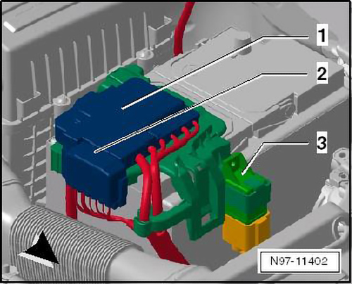
1 – control unit (BCM) for convenience system, gateway and onboard power supply
2 – retainer for control unit
3 – relay
4 – fuse
5 – relay plate
6 – fuse holder
7 – fuse holder
8 – flat fuse 19/2×5
9 – flat fuse 10/2×2,8
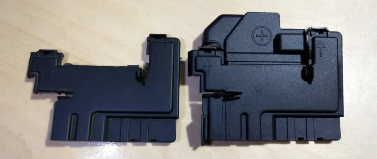
10 – cover for fuse holder
11 – semi round bolt (combi) with hexagon socket head
12 – assembly tool for blade fuse
13 – retainer for fuse socket
14 – adapter (PR-TW0)
15 – control unit for glow plug (PR-TF3,T1S/PR-TS4)/ contact close relay additional coolant pump J496 (PR-TW0) / relay 449
16 – central protection
17 – fuse (110A)
18 – hexagon nut with washer (M6)
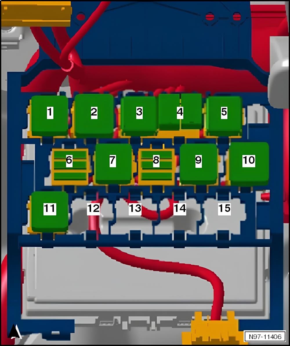
Relays
Relay carrier, from May 2009
- 1 – Low heat output relay -J359- (53)
- 2 – High heat output relay -J360- (100)
- 3 – Terminal 30 voltage supply relay -J317- (109)
- Models with engine code CGGB only
- 3 – Current supply relay for Simos control unit -J363- (429)
- 3 – Motronic current supply relay -J271-
- 4 – Dipped beam relay -J331- (449)
- Position left
- 4 – Fuel supply relay -J643- (404)
- Only models with petrol engine
- Position right
- 4 – Fuel supply relay -J643- (449)
- Only models with diesel engine
- Position right
- 5 – Voltage stabiliser 2 -J570- (505) 1)
- 6 – Fuse holder D -SD-
- See fuse concept
- 7 – Fuel pump relay -J17- (167)
- Only models with petrol engine
- 7 – Terminal 30 voltage supply relay -J317- (643)
- Only models with diesel engine
- 8 – Fuse holder E -SE-
- See fuse concept
- 9 – Starter inhibitor relay -J207- (53)
- 10 – X-contact relief relay -J59- (646)
- 11 – Headlight washer system relay -J39- (53)
- 12 – Terminal 75 voltage supply relay 1 -J680- (100) 1)
- 13 – Starter relay 1 -J906- (643) 1)
- 14 – Starter relay 2 -J907- (433) 1)
- 15 – Terminal 50 voltage supply relay -J682- (53) 1)
1) Only models with start/stop system
Relay carrier, from November 2009
- 1 – Low heat output relay -J359- (53)
- 2 – High heat output relay -J360- (100)
- 3 – Terminal 30 voltage supply relay -J317- (643)
- 3 – Current supply relay for Simos control unit -J363- (429)
- Only models with engine code CGPA
- Up to November 2010
- 4 – Dipped beam relay -J331- (449)
- Position left
- 4 – Fuel supply relay -J643- (404)
- Position right
- Only models with petrol engine
- 4 – Additional coolant pump relay -J496-
- Position right
- Only models with engine code CBZB
- To May 2010
- 4 – Fuel supply relay -J643- (449)
- Position right
- Only models with diesel engine
- 5 – Voltage stabiliser 2 -J570- (505) 1)
- 6 – Fuse holder D -SD-
- See fuse concept
- 7 – Fuel pump relay -J17- (449)
- Position right
- Only models with petrol engine
- 8 – Fuse holder E -SE-
- See fuse concept
- 9 – Starter inhibitor relay -J207- (53)
- 10 – X-contact relief relay -J59- (646)
- 11 – Headlight washer system relay -J39- (53)
- 12 – Starter relay 1 -J906- (643) 1)
- 13 – Starter relay 2 -J907- (433) 1)
- 15 – Terminal 50 voltage supply relay -J682- (449) 1)
1) Only models with start/stop system

Relay carrier, from May 2011
- 1 – Low heat output relay -J359- (53)
- 2 – High heat output relay -J360- (100)
- 3 – Terminal 30 voltage supply relay -J317- (643)
- 4 – Fuel supply relay -J643- (404)
- Position right
- Only models with petrol engine
- 4 – Fuel supply relay -J643- (449)
- Position right
- Only models with diesel engine
- 5 – Voltage stabiliser 2 -J570- (505) 1)
- 6 – Fuse holder D -SD-
- See fuse concept
- 7 – Dipped beam relay -J331- (449)
- Position left
- 8 – Fuse holder E -SE-
- See fuse concept
- 9 – Starter inhibitor relay -J207- (646)
- Position right
- 10 – X-contact relief relay -J59- (646)
- 11 – Headlight washer system relay -J39- (53)
- 12 – Starter relay 1 -J906- (643) 1)
- 13 – Starter relay 2 -J907- (433) 1)
- 15 – Terminal 50 voltage supply relay -J682- (449) 1)
- Position left
- 15 – Heater element relay -J925- (404)
- Position right
- A – Fuses in relay plate fuse holder -S3-
1) Only models with start/stop system
Relay carrier, from November 2011
- 1 – Low heat output relay -J359- (53)
- 2 – High heat output relay -J360- (100)
- 3 – Terminal 30 voltage supply relay -J317- (643)
- 4 – Fuel supply relay -J643- (404)
- Position right
- Only models with petrol engine
- 4 – Fuel supply relay -J643- (449)
- Position right
- Only models with diesel engine
- 5 – Voltage stabiliser 2 -J570- (505) 1)
- 6 – Fuse holder D -SD-
- See fuse concept
- 7 – Dipped beam relay -J331- (449)
- Position left
- 8 – Fuse holder E -SE-
- See fuse concept
- 9 – Starter inhibitor relay -J207- (646)
- Position right
- 10 – X-contact relief relay -J59- (646)
- 11 – Headlight washer system relay -J39- (53)
- 12 – Starter relay 1 -J906- (643) 1)
- 13 – Starter relay 2 -J907- (433) 1)
- 15 – Terminal 50 voltage supply relay -J682- (449) 1)
- Position left
- 15 – Heater element relay -J925- (404)
- Position right
- A – Fuses in relay plate fuse holder -S3-
1) Only models with start/stop system
Relay carrier, from May 2012
- 1 – Low heat output relay -J359- (53)
- 2 – High heat output relay -J360- (100)
- 3 – Terminal 30 voltage supply relay -J317- (643)
- 4 – Fuel supply relay -J643- (404)
- Position right
- Only models with petrol engine
- 4 – Fuel supply relay -J643- (449)
- Position right
- Only models with diesel engine
- 5 – Voltage stabiliser 2 -J570- (505) 1)
- 6 – Fuse holder D -SD-
- See fuse concept
- 7 – Starter inhibitor relay -J207- (646)
- Position right
- 7 – Dipped beam relay -J331-
- Position left
- 8 – Fuse holder E -SE-
- See fuse concept
- 9 – Not assigned
- 10 – X-contact relief relay -J59- (646)
- 11 – Headlight washer system relay -J39- (53)
- 11 – Terminal 75 voltage supply relay 1 -J680-
- 12 – Starter relay 1 -J906- (643) 1)
- 13 – Starter relay 2 -J907- (433) 1)
- 15 – Terminal 50 voltage supply relay -J682- (449) 1)
- Position left
- 15 – Heater element relay -J925- (404)
- Position right
- A – Fuses in relay plate fuse holder -S3-
1) Only models with start/stop system
Relay carrier, from May 2013
- 1 – Low heat output relay -J359- (53)
- 2 – High heat output relay -J360- (100)
- 3 – Terminal 30 voltage supply relay -J317- (643)
- 4 – Fuel supply relay -J643- (404)
- Position right
- Only models with petrol engine
- 4 – Fuel supply relay -J643- (449)
- Position right
- Only models with diesel engine
- 5 – Voltage stabiliser 2 -J570- (505) 1)
- 6 – Fuse holder D -SD-
- See fuse concept
- 7 – Starter inhibitor relay -J207- (646)
- Position right
- 7 – Dipped beam relay -J331- (449)
- Position left
- 8 – Fuse holder E -SE-
- See fuse concept
- 9 – Headlight washer system relay -J39- (53)
- 10 – X-contact relief relay -J59- (646)
- 11 – Not assigned
- 12 – Starter relay 1 -J906- (643) 1)
- 13 – Starter relay 2 -J907- (433) 1)
- 14 – Engine component current supply relay -J757-
- From June 2013
- Only CBLJ
- 15 – Heater element relay -J925- (404)
- Position right
- A – Fuses in relay plate fuse holder -S3-
1) Only models with start/stop system